MDY-type hydraulic cotton baler hydraulic system
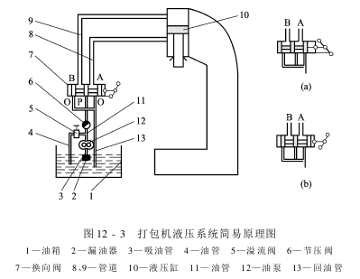
The hydraulic system consists of a hydraulic station, hydraulic cylinder, oil pipe, etc., as shown in Figure 12-3.
The electric motor drives the oil pump to rotate, forcing the oil from the oil tank 1 through the oil leaker 2 and the oil suction pipe to the oil return pipe through the pump 12, and then through the throttle valve 6 to the reversing valve 7. The throttle valve is shown in Figure 12-3 (b) position, the pressure oil enters the upper chamber of the hydraulic cylinder 10 from port B through the pipe, pushing the piston to push down the pressure rod head. The oil in the lower chamber of the hydraulic cylinder returns to the tank from the pipeline through the hydraulic reversing valve at port A and through port O. The relief valve is used to adjust the working oil pressure, the pressure relief valve controls the lifting and lowering speed of the pressure head, and the reversing valve is used to change the direction of the pressure rod head. When in the position shown in Figure 12-3(a), oil with a certain pressure enters the lower chamber of the cylinder and the pressure head lifts. When in the position shown in Figure 12-3(b), oil cannot enter the upper and lower chambers of the cylinder, and the pressure rod is stationary.
The main components and functions of the hydraulic transmission system:
(1) Power component: The function of the hydraulic pump is an energy conversion device that converts mechanical energy into hydraulic pressure energy.
(2) Actuator: oil cylinder and oil motor. Its function is an energy conversion device that converts oil pressure energy into mechanical energy.
(3) Control components: various control valves. In order to meet the needs of transmission performance, the operating components adjust the pressure, flow and direction of the liquid flow in the system.
AAAVEGTRHYTJ


